Rolling Plague
Several years ago I bought a broken remote-control truck toy for a buck at a school fund raiser. I knew I wouldn't get the RF part working again, but the chassis had wheels and motors that looked like they were in good condition. I took the thing apart and verified all I had to do was power the wheels in the back to get them spinning, and apply pos/neg voltages on the wheels in front to get them to turn in either direction. I bought some L293D chips so I could flip directions on the motors and had plans to hook it up to an Intel Edison. The project fizzled out though because the Edison didn't have very good support and it was a pain to connect up your own parts to it.

A few weeks ago I got interested in I/O with the Raspberry Pi and decided I should revisit the RC car project. Rather than breadboard it up, I decided I should just buy a Motor Hat board for the car and be done with it. This morning I finally got the whole thing together- I'm calling it Rolling Plague, since I wound up using a copy of Camus's The Plague to lift the controller off the wheels. Plus, everything is absurd.
Parts List
It took a while to pick out the right parts for this project. The main things were:
- Raspberry Pi Zero W: Since this is an embedded project, I bought a Pi Zero W kit with the usual accessories. The Pi doesn't have to do much (handle a wireless connection and run I2C commands to the motors), so the smaller low-power board was appealing. I wanted the WH board, but didn't find it for cheap anywhere.
- UGEEK Stepper Motor Hat v0.2: There are a few Motor Hat boards on Amazon (I assume most are clones of the one from Adafruit). While all I needed was something to control the DC motors, I thought it would be nice to have one that could also drive multiple servos (maybe I'll put a multi-axis camera mount on it later and see what's under my house). The UGEEK hat (see AliExpress) has a sourceforge repo with some drivers and docs (well written, too).
- 4xAA Battery Pack: The Motor Hat needs an external power source to drive the motors. I picked a simple 4xAA battery pack (w/ on/off switch) so I could get 5v. It works, but the front wheels seem to need more power.
- 1300mAh USB Battery: To power the Pi I'm using a USB power bank (we bought this a while back as a backup for phones). It can source enough power to run the Pi, but I know the Pi3 board often complains about being lower than the recommended amount. The Pi can run for hours off this battery.
Hooking things Up
The biggest pain in this project was soldering the pins onto the Pi Zero board. I've never been great at soldering and the pitch is small enough that I had to get a magnifying glass out to do the soldering given my old eyes. I continuously felt like I was ruining the board. However, the board booted when I applied power, and the power/ground pins at least seemed to work ok. For this project all I really needed was the I2C pins to work, so I didn't test out all the gpio pins. I'm pretty sure this will be the last time I ever solder headers on though. If the WH version had been available. I would have gone with that.
I booted the Pi up with the stock Raspbian Stretch Lite image and used a TV/keyboard to setup the OS. I used raspi-config to set the keyboard to US, connect to my wireless router, enable sshd, and enable I2C drivers. The motor hat's sample code needed smbus to run (I may have pip installed it, but you can apt-get python3-smbus). Once ssh was running, I detached the Pi from the TV and switched to using a chromebook to connect to it via ssh. The Zero was sluggish at times, but its python was good enough to issue io commands.
The wiring for the board was pretty easy to hook up. I plugged the 5V batter lines into the HAT and then ran the DC motor lines into M1 and M2 on the board. I also hooked up a servo and tested it out with the example programs. Their library did all of the work of setting up the controller over the I2C. All I needed to do was issue some python commands on the Pi to get it to turn left and right. I did the same things with the DC motors. Basically you set the speed of a DC motor (0-255) and then send a direction command to tell it which direction to spin (forward, reverse, or disengage). The chipset sends a PCM sequence that throttles how much voltage is seen by the motor (averaged over time). It was pretty thrilling to see the back motors spin up and go. They needed a value of 30 or so to get going.
Back and Forth
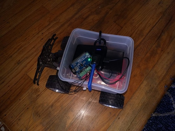
I didn't want the electronics to get smashed so I put them in a small plastic bin that I could strap to the chassis. The bin didn't quite clear the wheels, so I grabbed a paperback version of The Plague and stuck it between the chassis and the bin. The whole thing is strapped together with a shock cord.
I set the back motor to the minimum power setting and told it to go forward. It immediately went backwards (I hadn't bothered to figure out polarity) and ran into something. I flipped the wires around and issued a few commands to go forwards and backwards. The extra weight of the batteries (and Camus) meant I had to provide a higher value (around 40) to the monitors to get the car going. Similarly, the front wheels didn't turn very sharply, even when using the top value (255). I'll probably need to increase the battery voltage to get it to work a little better.
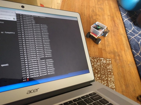
Driving the car was pretty clunky, largely because I had to issue multiple commands to get each motor to change state (ie, set speed and then enable/disable the motor). My kids started driving their RC cars around me and there was no hope of me keeping up. I'll need to come back later and write some functions to simplify the driving.
Naming
In retrospect, Camus's book seems like an appropriate choice for this project. It's pretty ridiculous to put all this effort (and money) into building an RC car that's nowhere near as usable as a $10 car from a toy store. Still, it's important to keep doing the things you do, no matter how absurd they are.