|
|
| Craig Ulmer |
FAODEL 1.2108.1 ReleasedI am happy to report that we (finally) shipped the "Fluid" release of FAODEL on Github this week. Looking back now, it's been over two years since our last external release. We had intended to make the updates available last year after our big milestone project with SPARC completed, but we ran into a number of chicken-and-the-egg problems with other software libraries (eg, we can't test our release until you release updates that use our release). It also didn't help that we added a few new featured while waiting on the release logistics to work themselves out. Continually adding "just one more thing" winds up resetting the release process a lot, which is lengthy when you have to test against multiple platforms, multiple nics, and multiple software stacks. Todd Kordenbrock did an excellent job of working out all the painful details and finalizing everything. Thanks, Todd!  Highlights of New FeaturesI'm really pleased with some of the new features in this release:
The following are the more terse release notes from NEWS.md: Release Improvements
Significant User-Visible Changes:
Experimental Features
| A Few Photogrammetry Experiments with MaxWhile 3D printing bones from CT scans was fun, what I'd really like to do is scan in ordinary objects that I could manipulate and print. Professionals that do this kind of scanning use expensive LiDAR scanners or setup special rooms with calibrated camera arrays. Intel's RealSense L515 camera looked like it would be a promising, lower-cost LiDAR camera, but Intel just announced that they're killing off all the RealSense products (yet another failed intel product line). Apple's phones and tablets with LiDAR sound like what I need, but I just can't force myself to buy anything from Apple (not even that laptop that thieves just ordered with my credit card and shipped to my house by mistake!). That leaves me with plain old photogrammetry from images. QlonePrevious experiments with Meshroom left me feeling like I could get some good results, but only if I put a lot of effort into doing the photography right. In hopes of finding something that was more integrated with a phone, I skimmed websites and found some positive reviews of an Android app named Qlone that could scan simple objects using just a phone. The clever part about their approach is that they use a specially formatted mat that you print out to help orient the camera. I downloaded the free version of the app, printed the map, and set off to scan in an old Max Headroom candy container I bought from a gas station back in the eighties (interestingly, someone else has already scanned this in and posted it to thingiverse). 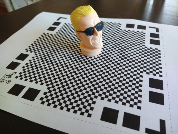 One of the nice things about Qlone's approach is that the mat makes it possible for the camera to figure out its orientation in real time. It renders a dome over your camera view while you're scanning so you can see what angles need to be done. While I initially tried moving the phone around the object to get all the pictures, it was a lot easier to hold the camera at one orientation and then just rotate the mat. Once the app had pictures from all angles, it went through the math to chip out a 3D model. While the model did look like Max Headroom, the quality was pretty low. This might have been because the subject was plastic (photogrammetry has trouble with glossy surfaces), but I'd also suspect its difficult to get good results out of a phone app.  The free version didn't have a way to export the model in a useful way, so the only result I have is this gif. The app baited me with a "buy in the next 20 minutes and get a discount" option. I declined though, figuring anything with a time-limited sale like this probably isn't worth it. While I really liked the user interface for this tool, it didn't produce results that would be good enough for printing. Back to MeshroomI decided to hunker down and spend some time experimenting with how to take pictures that would be better for meshroom. People online suggested using a prime lens and constant camera settings, so I impaled Max on a pvc pipe, set him up in my garage, and the did a sweep of pictures using my Canon D77 with a 50mm EF prime lens. I (wrongly!) guessed that I should use a low f-stop (ie, F/1.8) to maximize the blur in the background, hoping that this would make it easier for Meshroom to pick out the foreground. About midway through the pictures I realized that the lighting wasn't very even in the garage and that several of my photos were out of whack due to me having to step around junk sitting around my garage. As I feared, Meshroom was only able to infer about half of Max's head. I moved Max's pipe outside and did another round of pictures in the sunlight.  Meshroom did a much better job reconstructing Max with the second round of pictures. The results are bumpy, but the general shape is there with a decent amount of detail. I was impressed at how well it found the lines in the glasses and the creases in his forehead.  Scan ProblemsWhile the scan looks pretty good visually, you begin to see more of the flaws when you take away the texture map and just look at the durface mesh. If you look at the arms of Max's glasses below, you'll notice that the mesh doesn't know there's a space between the glasses and his face. The texture map adds some color shading to the triangles that makes it look like the glasses are floating and casting a shadow on his skin. Unfortunately, I need the mesh to look good by itself if I want to make a good 3D print.  It's difficult for photogrammetry software to recognize separations like this without a lot of supplemental pictures that aim through the gap. If I wanted to scan Max in the right way, I'd probably pull the Max figure apart and scan each item separately. I'd probably also spray him with something to make the plastic less reflective. This is more work than I want to put into it right now. Reading through some other web pages, I've realized that I got my camera settings backwards: primes are good for consistency, but the background should not be blurry. A presentation at the Slade School of Fine Art on Photogrammetry recommended an f-stop of F/8.0 as a starting point. Given the number of pictures that Meshroom threw away, I suspect it's useful to have some background detail to help figure out what's going on in the foreground. In any case, these are all good ideas to try out another day. FilesHere's a copy of the mesh and textures: maxmesh.tar.xz | 3D Printing My Pelvis from a CT ScanA few months ago I bought my son a Creality LD-002H Resin 3D Printer so we could play around with printing some simple objects. Like most people, we watched a lot of videos to get a better handle on how to (safely) work with resin, printed a bunch of example objects from Thingiverse, and then watched more videos to figure out how to make better prints. While printing models has been fun, I'd really like the kids to get a better handle on how to create their own objects through photogrammetry tools like Meshroom or editors like Blender. 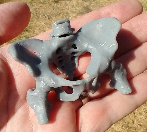 The last few weeks I've been working through the details of how I could convert and CT scan of me into something I could print. Through a combination of open-source tools I was able to generate a mesh model of my pelvis and print a small version of it. I seem to forget how to use all these tools after a few days, so this post is just some notes for me to be able to recreate the process in the future. 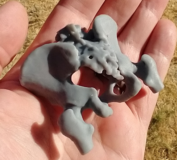 Viewing CT Data in 3D SlicerBack in 2013 I had to go to the hospital because I had a bad infection that needed surgery. The doctors ran me through a CT machine to get a better view of what was happening inside me. After my surgery I learned that Kaiser will burn a CD with your data on it for only $20 if you ask them. Being curious, I ordered a copy and poked around with it for a bit. While the data isn't in a format that I recognized, a viz friend pointed me at a tool called 3D Slicer (based on VTK) that's designed to look at medical data. It's a little confusing to get started, but you basically:
I always stumble around with the default view settings. Usually the problem is that I haven't loaded a DICOM entry with anything in it (eg, a patient record) or I forgot to tell Slicer to view the data by turning the volume's closed eye into an open eye. Once the 3D data shows up, I switch to a 3D-only view by selecting View and Layout.  Extracting and Smoothing ContoursWhile the volume rendering tool is a nice way to poke through the data, what you really need to do is extract the contour for the bone so you can extract it as a mesh (ie, isosurfacing). To do this you need to run the Segmentation tool to build a mesh and then smooth it to make it more printable.
It took some trial and error to find a threshold value that produced a good view of my pelvis (too low and you get tissue, too high and the bone starts disappearing). The two main issues I saw with segmentation were that some regions had small holes and some curving regions were bumpy like corduroy. Selecting the Smoothing option from the Segmentation options helped fix some of these problems. I'm sure you could do a lot more here to fix things- some of the videos I watched showed how to get precise segmentation by hand labeling points. I'm not printing an actual hip replacement so I didn't go into to much detail. Once I was done I clicked on the Segmentations button and exported to STL.  Cleanup in MeshlabI pulled the STL file into MeshLab to verify it looked ok in another meshing tool and do some additional cleanup. While I think Slicer can do this cleanup, MeshLab seemed like an easier way to make some hand edits. I looked around in the mesh and manually removed some leftover polygons.  Adding Supports in ChituboxThe final step for me was to load the model into Chitubox to turn it into printable object. Chitubox is pretty amazing- it'll analyze an object and figure out what supports would be added to make it printable on a 3D printer. My neighbor does a lot of 3D printing and gave me a lot of tips on making good prints with Chitubox. eg, Make the back side of the model face the build plate so the supports don't leave bumps in important places, angle the structure to make it easier to build, use the skate support platform shape to make it easier to remove, etc.  I manually placed the pelvis model and rotated it slightly, but pretty much used the default settings everywhere else. Even with a ton of supports, Chitubox still wasn't too happy with the printing risk. Once it was done I adjusted the print's first layer exposure time to 60s and the remaining layers to 6s. Based on previous prints, if you don't expose the first layer for long enough it doesn't stick to the build plate and your print fails. 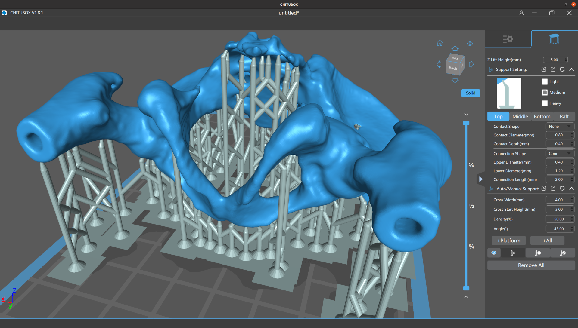 Printing, Cleaning, and CuringThe final step was to take the model to the printer and print it out. Resin printing is a pretty messy and dangerous process. You align the print head (crucial!), pour resin into the vat, load the vat into the printer, and then print the model. This print took about four hours, but I didn't have to babysit it after I verified the first few layers had stuck. When it finished, I chiseled the part off the build plate and dropped it in a pickle jar (w/ strainer) filled with isopropyl to clean off the uncured resin. After a lot of shaking, I took it out and clipped off all the supports (which is unusually satisfying). From there I did another quick rinse in isopropyl, patted it down with paper towels, and put it under a UV light to cure it. I'm still new to 3D printing but I think it looks pretty decent. The main problem with this print is that I scratched it up quite a bit when I was cleaning it up with paper towels (the print is still pretty soft at this point). In the future I'll probably buy a curing station which simplifies a lot of the cleaning and curing problems. The other problem with the print is that there are some extra holes in the back because I set the contouring threshold value too high. At least that's what I hope- maybe I just have really thin bones. Safety and CleanupI should point out that the resin I'm using is toxic when uncured and it's important to follow safety procedures when doing this kind of printing. I wear disposable nitrile gloves and safety classes whenever I work with uncured resin, and crack the garage door to help vent the area. When it comes time to handling wet prints my neighbor suggested a practice of having one clean hand and one dirty hand, since there's always something you need to grab and you want to minimize what gets dirty. I use an excessive amount of isopropyl to clean up the build plate, vat, and tools when I'm done. Fortunately, you can just leave all the dirty towels and gloves in the sun for 30mins to cure them and make them safe for disposal. | Performance of the BlueField-2 SmartNICRecently I've been working with Carlos Maltzahn at the University of California, Santa Cruz (UCSC) on a new DOE ASCR project that is exploring how programmable network interface cards (or SmartNICs) can be used to improve data management services in HPC/HPDA platforms. To get a better idea of what current hardware can do, Jianshen Liu conducted a number of network and CPU experiments on NVIDIA BlueField-2 SmartNICs located in NSF's CloudLab. While the ARMs on these cards are slow compared to modern host processors, they are sufficient for performing the kinds of operations we routinely need in the I/O space. Jianshen summarized what we learned in the following arXiv paper (UUR SAND2021-5854R).  AbstractHigh-performance computing (HPC) researchers have long envisioned scenarios where application workflows could be improved through the use of programmable processing elements embedded in the network fabric. Recently, vendors have introduced programmable Smart Network Interface Cards (SmartNICs) that enable computations to be offloaded to the edge of the network. There is great interest in both the HPC and high-performance data analytics communities in understanding the roles these devices may play in the data paths of upcoming systems. This paper focuses on characterizing both the networking and computing aspects of NVIDIA's new BlueField-2 SmartNIC when used in an Ethernet environment. For the networking evaluation we conducted multiple transfer experiments between processors located at the host, the SmartNIC, and a remote host. These tests illuminate how much processing headroom is available on the SmartNIC during transfers. For the computing evaluation we used the stress-ng benchmark to compare the BlueField-2 to other servers and place realistic bounds on the types of offload operations that are appropriate for the hardware. Our findings from this work indicate that while the BlueField-2 provides a flexible means of processing data at the network's edge, great care must be taken to not overwhelm the hardware. While the host can easily saturate the network link, the SmartNIC's embedded processors may not have enough computing resources to sustain more than half the expected bandwidth when using kernel-space packet processing. From a computational perspective, encryption operations, memory operations under contention, and on-card IPC operations on the SmartNIC perform significantly better than the general-purpose servers used for comparisons in our experiments. Therefore, applications that mainly focus on these operations may be good candidates for offloading to the SmartNIC. Publication
| Low-Flying Military Plane over Livermore2021-03-28 planes
There was a lot of talk on local social media this week about a large military plane that flew over Livermore at a very low altitude. The town is already wound up about larger planes flying into Livermore because there's an expansion plan being discussed that would allow private charter 737s to land at the airport. Seeing a massive, loud military plane flying low over town made everyone wonder if that's what daily life is going to be like in the next few years.  There was a lot of speculation about what was going on with this flight. Some people thought it was emergency vaccine supplies being dropped off. Others claimed it was a military salute for a Lt. Col. in Pleasanton who was just awarded the Distinguished Flying Cross. In the end it turned out to be a C-17 Globemaster doing a practice landing approach at our municipal airport (see Brodie Brazil's video of the approach). Tracking SOUND87I went to my PiAware node and pulled the day's data to see what military flights took place on Wednesday. I found AE07E0 was active around the 4pm time period people were talking about. Interestingly, the flight used the call sign SOUND87, which made me wonder if this was some kind of sound test for the airport extension (I doubt it now- it seems like a routine test). As the below plots show, the plane flew in from the east, passed the airport, and made a sharp turn north. Zooming in on the east side of town, I noticed it flew right over LLNL at about 2K ft, just a block away from their $3.5B national ignition facility (NIF). I'd thought they had a no-fly zone over them, but that seems to only be for drones. Here is the raw data for the flight.   Debunking the Salute TheoryThe idea that the military would dive bomb a city to show its appreciation of a soldier bothered me, so I went to FlightRadar24 and pulled up the data for the whole flight. As seen below, they took off from Vegas, circled the bay area, and then dropped in on Livermore. After that, they flew north to Concord and did a similar practice approach at Concord's municipal airport (CCR) before landing at Travis AFB. Given that they didn't fly anywhere near Pleasanton and they made a second drop somewhere else, I'd guess this has nothing to do with the Lt. Col's award.  Questioning the Airport ExpansionOne thing this flight really highlights is that Livermore people will notice larger planes flying to our airport. While the C-17 is much bigger and louder than the 737s the expansion is targeting, it made a lot of people realize that the airport approach really does stretch all the way across town, starting at the $3.5B big science experiment at the lab. I hope enough people stand up to the FAA and prevent larger planes from being able to land there. |