The other week while working in the back yard I noticed there were a surprising number of crows watching me from the neighboring yard. There were enough of them that I thought I should count them, but didn't because I knew they'd fly away before I'd finished. I took a picture instead and vowed that I'd ask the vision LLMs to tell me how many crows they could see. This task is interesting to me because it involves both object recognition and simple counting. I suspected that the models would easily recognize there were birds in the picture, given that the previous post found visual LLMs could identify people, places, and even inflatable mascots. However, I doubted that the models would be able to give me an accurate count, because they often have problems with math-related tasks.

How many crows do you see? 25?
I've gone over the picture and put red circles on all the crows I see (no, there aren't two by the pole. Zoom in on the bigger image to see its old wiring). My crow count is 25.
Traditional YOLO Struggled
Counting items in a picture is something that Computer Vision (CV) has done well for many years, so I started out by just running YOLO (You Only Look Once) as a baseline. I didn't want to spend much time working this out so I asked Gemini 2.5 Flash to generate some python code that uses a YOLO library to count the number of crows in an image. Interestingly, Gemini was smart enough to know that the stock YOLOv8 model's training data (COCO) didn't include a specific "crow" class, so it changed the search term to "bird". The initial code it generated ran fine, but didn't find any birds in my picture. I bumped up the model from nano to medium to extra large (x). The largest model only found one bird with the default settings, so I lowered the confidence threshold from 0.5 to 0.1. The change enabled YOLO to spot 17 out of 25 birds, though some of the lower-confidence boxes looked questionable.

YOLO Birds at 0.10 Confidence
Previously I've had success with YOLO-World when using uncommon objects because it is much more flexible with search terms. However, when I asked Gemini to change the code over to YOLO-World, the extra large model with 0.10 confidence only identified 10 birds. Looking at the code, the only significant difference was that the search terms had been expanded to include both bird and crow. Switching to crow alone only had 4 hits. YOLO-world took longer to run than plain YOLO (eg 8s instead of 4s) so it's disappointing that it provided worse results. To be fair though, a lot of the birds just look like black bundles of something floating around the sky.
Gemini 2.5 Answer
Before going into how well local vision LLMs could perform, I went to Gemini and asked 2.5 Flash how many crows were in the picture. It initially answered "20-25" birds, but when I asked for a specific number it increased the count to 30-35 crows. When I then asked it to count individual crows it said 34 individual crows. It sounded reasonable, so I asked it to put a bounding box around each one. As the below image shows, it added the boxes, but at the same time it also inserted a bunch of new crows into the image. This answer is pretty awful.

Crow Count, Now with More Crows
Switching to Gemini 2.5 Pro changed the number to 23 crows. However, asking it to place boxes around the crows resulted in crows being added to the picture. Additionally, the boxes contained multiple crows in each box.
Local Models
Next, I used Ollama to do some local testing of Qwen2.5-VL, Gemma3, and Llama3.2-vision on my test image. I tried a few different prompts to see if I could trick the models into giving better answers:
A. How many crows are in this picture?
B. Very carefully count the number of crows in this picture.
C. Very carefully count how many birds are in this picture.
                    A.  B.  C.
qwen2.5vl:7b        14  20  20
gemma3:12b-it-qat   14  19  17
llama3.2-vision:11b  3   2   0
Qwen and Gemma did ok in these tests, especially when I asked it to put a little more effort into the problem. Theorizing that the libraries might be downsizing the images and making the small crows even harder to recognized, I cropped the original test image and tried the prompts again (note: the cropped image is at the top of the page. The original image was zoomed out like the boxed image above). As seen below, the cropped image resulted in higher counts for both Qwen and Gemma.
A. How many crows are in this picture?
B. Very carefully count the number of crows in this picture.
C. Very carefully count how many birds are in this picture.
                    A.  B.  C.
qwen2.5vl:7b        20  25  25
qwen2.5vl:32b       24  30  24
gemma3:12b-it-qat   25  32  30
llama3.2-vision:11b  0   0   2
The frustrating part about working with counting questions is that you usually don't get any explanation into how the model came up with that number. I did notice that when I switched to the larger, 32B Qwen model, the LLM would sometimes give me some positional information (e.g., "1 crow near the top left corner", "2 crows near the center top", etc). However, the number of crows in the list was never the same as the number that it reported back as its final answer (e.g., 21 vs. 30). When I compared the answers with what I see in the picture, I think the locations are definitely swizzled (e.g., it should be 2 in the top left, none in the center).
Thoughts
So, not great but not terrible. I'm impressed that the home versions of Qwen and Gemma were able to come up with answers that were in the right ballpark. It is troubling though that the models generated believable-looking evidence for their answer that was just wrong. I'm more bothered though by the visual results where crows were added to better match the answer.
One saving feature for Qwen that I'll have to write about later though is that it is designed to be able to produce bounding boxes (or grounding) for detected objects. I've verified that these boxes are usually correct, or at least include multiple instances of the desired item. I feel like this should be an essential capability of any Visual LLM. We don't need any hallucinations, uh, around here.
A few months ago I got more serious doing AI things at home and switched from using online services (Gemini and OpenAI) to locally-hosted models. While the change was partially motivated by a desire to ween myself off the big AI companies, I've also been wanting to do something with the unused GPU that my son left behind when he went off to college. I initially went down the HuggingFace path of manually downloading models and using the Transformers library to code up everything. More recently I've switched to using Ollama, which automates the whole process and gives a nice OpenAI API that I can talk to with code or hook up to OpenWebUI. My son's 12GB RTX3080 barely qualifies as an entry-level GPU for AI work, but it's good enough that 3-5B parameter models are fairly responsive.
Lately I've been looking into how well vision models like Qwen2.5-VL and Gemma3 can summarize images. My motivation for this is that eventually I'd like to scan my home photos and have a vision LLM write a one-line text summary of each picture so I could then search for things via grep. Since I won't be getting a larger GPU anytime soon, I've been experimenting with smaller models like qwen2.5vl:7b, gemma3:12b-it-qat, and llama3.2-vision:11b. While Qwen is the only one that really works well with 12GB of VRAM, the other are small enough that my son's 8-core CPU can process prompts in 10-30 seconds. In this post I wanted to capture some of my observations on quality when using these smaller models.
Simple Prompting
After some trial and error, I settled on the below prompt. There's a battle story in every clause of that prompt. I initially started with something similar to "describe this picture", but quickly found that all the models generated lengthy paragraphs about the image, usually with irrelevant details, extra formatting, and lead-in sentences (e.g., "Here is a description of the image:"). The "no formatting" helped remove all the markdown formatting and took away some of the writing primitives for organizing content into bullet lists. Next, adding "single sentence" usually helped constrain the models to limit their responses. Finally, adding concisely helped some of the models choose their details more carefully. While I noticed that concisely sometimes caused a model to omit key details it had reported in previous responses, I appreciate having the answer boiled down to as short a form as possible.
Write a single sentence with no formatting that concisely
describes this picture.
Front Page Images
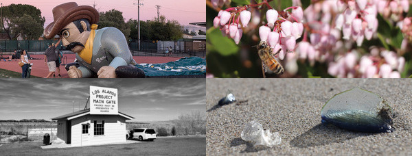
For testing, I used a few of the images that I've previously posted on the front page of this website. I wanted to pick images that the models had not seen before, as I've seen cases where a bad vision model can extract just enough information that a good LLM can build out a long and convincing text response. Below is a collage of the pictures I used. For each image I ran the above prompt multiple times to get a general idea of how well the models were working, and then extracted the responses for all the models in the last run.
Rex the Inflatable Cowboy
The first image I tried out was Rex, an inflatable cowboy that they use for the Livermore football team. It's a good test image because it's a common thing you'd see at sporting events, but it's not quite inflated in a way that makes it clear what's happening. Below are the answers the models gave me. Qwen and Gemma both did well, though Gemma thought this was a tennis court. In runs before I added "concise", Qwen properly identified the cowboy was named Rex. I'm disappointed in Llama's answer. It didn't mention cowboy or inflatable, and thought Rex was holding a fishing rod.
qwen2.5vl:7b
  A large inflatable character resembling a cowboy is lying on the
  ground at a sports field during dusk.

gemma3:12b-it-qat
  A large, deflated inflatable cowboy mascot labeled "Rex" lies on
  a tennis court during sunset, surrounded by people.

llama3.2-vision:11b
  The image shows a cartoon-style illustration of a man with a large
  head and small body, wearing a brown hat and holding a fishing rod.
Fuzzy Bee
I expected the bee on a flower picture to be easy for the models to figure out because it's basic nature. While Qwen and Gemma did fine, I was disappointed that Llama did not identify the bee.
qwen2.5vl:7b
  A bee hovers near delicate pink flowers on a branch.

gemma3:12b-it-qat
  A honeybee is perched amongst a cluster of delicate pink flowers.

llama3.2-vision:11b
  The image depicts a close-up of a pink flower with yellow stamens,
  showcasing its intricate details and vibrant colors.
Project Gate
I like the Los Alamos Project Main Gate picture as a test because it has some easy-to-read text that can provide historical context. All three models extracted the text off the sign, though Llama only gave the first three words in all caps. Interestingly, Qwen and Gemma identified this as a black and white photo, while Llama identified specific features as being black or white.
qwen2.5vl:7b
  A black and white photo shows a small building with a sign
  reading "Los Alamos Project Main Gate" and a car parked nearby
  under a vast sky.

gemma3:12b-it-qat
  This black and white photograph shows a guardhouse and sign
  reading "Los Alamos Project Main Gate" with a car parked nearby
  against a backdrop of mountains and desert landscape.

llama3.2-vision:11b
  The image features a white sign with black text, which reads
  "LOS ALAMOS PROJECT" and is situated in front of a white building
  with a large window.
Curious as to whether the models could detect anachronisms, I asked some follow up questions involving dates. The models consistently reported that the photo was likely from the 1950s or 1960s, citing the history of Los Alamos, the style of the buildings, and the use of black and white photography. Qwen noted "the design of the car, with its rounded edges and distinct shape, aligns with vehicles from that time period." so I asked the below question about the car. I think it's interesting that when it focused on it more, it identified it as a minivan that is out of place.
What year was the car in this picture made?

  The image you've provided is a black and white photograph of a
  building with a sign that reads "Los Alamos Project Main Gate."
  This is a historical image, and the car in the picture appears
  to be a minivan, which was not a common vehicle in the early
  years of the Los Alamos Project. The Los Alamos National
  Laboratory was established in 1943, and the earliest minivans
  were introduced in the 1980s. Therefore, the car in the picture
  is likely from the 1980s or later, as it does not match the
  design of vehicles from the 1940s or 1950s, which were the
  time periods when the Los Alamos Project was active.
Jellyfish
The jellyfish picture seemed like a good test because the velella velella isn't all that common, but the beach should provide enough context for a model to estimate that it's probably some kind of jellyfish. Gemma did great. Qwen misidentified the jellyfish as glass. Llama didn't even realize this was the beach.
qwen2.5vl:7b
  Two pieces of glass lie on a sandy beach, reflecting light and
  surrounded by small grains of sand.

gemma3:12b-it-qat
  The picture shows several translucent blue jellyfish washed up on
  a sandy beach.

llama3.2-vision:11b
  This image depicts a close-up of a small, dark gray stone with a
  rough texture and a hole in the center, featuring a lighter
  gray interior.
Thoughts
Nontechnical people have seen or used enough AI tools that most people would shrug their shoulders and say "so what?" about these open models. The thing that is significant to me is that you can download them for free and use low-end GPU to perform image understanding tasks that would have been difficult to get done just a year ago. The commercial sites are much better and faster, but I don't want to send them my images or help the companies build up their empires more than I already have.
I was surprised at how much of a difference I saw in these small LLMs. Last Fall I started using Llama 3.2 because it was the next big step after CLIP. Llama's been my go-to model for image work because the text end has always felt solid and you can scale up to a massive number of parameters when you have the hardware. In the above tests though, I see that Llama was noticeably worse than Qwen and Gemma. It also took wandering walks that were off topic, which is a pain when you're trying to feed results into a large database.
I should emphasize that there's unfairness in these tests because the Qwen I used is only 7B parameters, while Gemma was 12B and Llama is 11B. The giant models for Llama and Gemma likely give better results, but again, I want to use the smallest model that I can. Looking forward, it'll be interesting to see how well Qwen3-VL does when it's released. When I plug the project gate picture into Qwen's online chat, the 32B parameter models automatically spot the minivan and estimate the picture was from the 1990's (update: this also worked in the 32B 2.5VL). Hopefully Qwen3 vision will have a smaller model that can do the same.
I hit a weird problem with Google's Gemini 2.0 this morning- I asked it to transcribe some images of hand-written notes into a CSV file and had it swap some of the lines. As someone that does a lot of data engineering, I find this especially dangerous because the output was convincing enough I almost didn't catch the error in the actual numbers. This makes me wonder how much bad data is going to flow into important records in the near future.
Transcribing Power Bills
This morning my wife and I were talking about how our power bills have gone up a bit in the last few years. When I asked if we had this in a spreadsheet somewhere, she said no, but pointed me at 5 pages of handwritten notes she had made over the years that concisely summarized all the data I'd need to make some plots. It occurred to me that this was exactly the kind of thing that AI should be able to do so I pulled up Gemini, typed the below prompt, and proceeded to take pictures of the notes.
I would like to convert 5 pictures of notes about my pg&e
gas bills into a csv file with the following columns: date,
dollar amount, electric amount, gas amount, PG&E code, Human
notes, and conversion notes. The human notes should be any
comments that were written in the entry. The conversion
notes should be any problems you came across while translating
a particular entry.
I then sent a picture of each page, with a statement about how this was the nth page. The response from the first picture was very reassuring: it printed out a CSV file that looked like everything was in the right place. The next few pictures appended more data to the CSV. Gemini said something went wrong on the last two pictures, so I switched to my chromebook, started a new conversation, and repeated the process until I got to the end. It even gave me a link for downloading the CSV file so I didn't have to copy paste it. I moved over to Google sheets, imported the CSV, and started asking Gemini to remind me how to do a pivot in sheets so I could look at the years in a monthly timeline.
Transcription Problem
The Sheets spreadsheet plots had some issues because of missing cell entries, so I went back and started manually inserting values. This is fine, as I'm happy to use any tool that automates 90% of the brute force work. However, as I went through the table, I noticed two problems. First, the gas numbers had some bad values because of my wife's handwriting (eg "g .55" became 8.55). This Brazil-like mistake is still fine, as the errors would be caught with some range checking. The bigger problem was that Gemini swapped a few of the data values in the lines:

A few mistakes
This problem is significant because it's hard to detect. It's also very puzzling because the image has a lot of guides to help keep things aligned: the original text is structured, each line has blue lines to guide the reader, and there isn't anything obvious to me that would trip it up. In fact if I just send the one page, it transcribes the data just fine. That makes me wonder if it's something to do with appending knowledge from one prompt to the next.
Dealing with Djinnis
This kind of problem is what leads to the endless prompt engineering cycle that is what makes AI so difficult to use these days in tasks that require accuracy. Should I just send 5 tasks to transcribe the images and merge them myself? Should I tell it valid ranges for the fields? Should I take a video and scan all the pages in one shot?
Prompt engineering feels like you're dealing with a Djinni that's granted you three wishes. There's always a loophole that wrecks your commands, so you spend more and more time perfecting additional clauses to your prompt to try to convince it to do the thing you want. In the end I'm not sure you can ever be certain that it's not stabbing you in the back in some unexpected way.
If everything is working right, you should be seeing this website rendered with a new backend that I've had on the back burner for a few years now. It's still missing some features, but I decided to switch over to it so I can move on to other projects. It's written in C++ this time, but still uses Emacs Org mode files for the content.
Evolution
Over the last 20+ years or I've implemented my website in a few different ways. Back in the 1990's I wrote a few web pages in HTML to talk about the things I was doing in college. HTML was tedious so I wrote some Perl scripts to generate static web pages from plain text files. Writing in plain text really helped speed up the writing, but after a few dozen posts it became a chore to regenerate and upload the content whenever there was a change. The next step was to port the Perl script over to a cgi script that could generate the pages on demand. While people scoff at it now, Perl was a pretty decent language for generating html because it was straightforward to hack together a bunch of regexs to convert chunks of text into HTML templates. It was hard to re-read the code and make sense of it, but since it was an interpreted language you could just iterate on it until things looked right.
The next big step for me was to reformat all the text content into an Emacs Org-mode file. Org mode made it easy to put each post as its own section in a single-file outline. Merging everything into one file meant I could insert extra posts into the timeline without having to renumber everything. Plus, the Emacs spell checker has been great, when I remember to run it. I updated the Perl cgi script to read from the org file and dump it to HTML. Looking back through my posts, I see I made that change 10 years ago.
Needing to Change
The Perl version of this website was ok, but a few things bugged me. First, the HTML looked a little old and didn't do the CSS magic to make the site readable on smaller devices. It was pretty awful on a cell phone because it would shrink several a wide desktop display of content down to a narrow device. Also, Google said at some point that pages that were missing a proper viewport tag (like mine) would be pushed down in their search results. Second, I noticed that generating my webpages with Perl took longer than I wanted. It could have just been the cheap webhosting plan I'd been using, but I suspected that all those complicated regexs I'd written were adding up. Finally, I wanted to do more things with the website but I don't write anything in Perl anymore.
So why C++? Most of my coding these days is in C++ so I had a good idea of how to split the code up into useful classes and implement some of the harder things like string formatting. The main hardship of going with C++ is that you have to recompile the code every time you make a major change. It took a while before I found the right balance in the code. Initially I went all-in on jamming everything except the org-mode content into C++. I wasted a lot of time working out clever ways to have CMake generate custom header files with constants for the different sites I wanted to run (ie, devel at home and production on the site). I later came to my senses and switched to a system that has hooks to read in a template file at runtime, so I could change the look of the website without having to recompile everything.
Changes
I don't think the site looks too different, but there are some changes:
- Quicker: I haven't done any speed testing, but the site feels a lot peppier now.
- Mobile Friendly: Things should look ok on a cell phone now. The new CSS should just scroll vertically and be readable.
- Simple Header: I'm still doing a horizontal scroller, but I've shrunk the navigation controls to a command bar.
- Separation of Content: Someone suggested that I split the site content so that it was clear what I do for work and what I do in my personal time. The new software made it easy to run each one as its own blog, so I created a "Publications" section and a "Hobbies" section.
- Longer URLs: Sadly, I had to break the way I was linking to posts. One problem was that since there wasn't a date in the previous version of the URLs, I couldn't have the same title more than once. Changing URLs was a sin in the old web, but seriously, how many people linked here anyways?
There's still a lot missing (eg index and tags pages), but it's good enough that I've switched things over. If you can't find a page you're looking for, flip around some and use the date to find the new post.
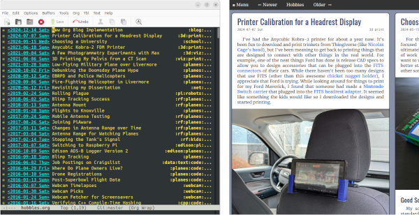
I've had the Anycubic Kobra-2 printer for about a year now. It's been fun to download and print trinkets from Thingiverse (like Nicolas Cage's head), but I've been meaning to get back to printing things that are designed to connect with other things in the real world. For example, one of the neat things Ford has done is release CAD specs to allow you to design accessories that can be plugged into the FITS connectors of their cars. While there haven't been too many designs that use FITS (other than this awesome chicket nugget holder), I appreciate that Ford is trying. While looking around for things to print for my Ford Maverick, I found that someone had made a Nintendo Switch carrier that plugged into the FITS headrest adapter. It seemed like something the kids would like so I downloaded the designs and started printing.
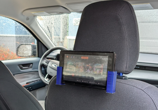
Rob Stu's Nintendo Switch holder for FITS
Calibration Problems
The first headrest adapter print came out fine, but when I went to try it out on my truck I found that the holes were a little small for my posts. Thinking it was just some residual plastic in the hole, I pushed one of the posts through its hole by twisting it through. Given that the twisting weakened the arm a little and there was no way to push the second post through, I decided something was wrong with the dimensions. I used calipers to measure and compare the print and headrest. In addition to the holes being small, I noticed that some features of the print were just a little smaller than round numbers (eg 49.3mm for the adapter block). I'm not great at Blender but some quick measurements on the original model confirmed the print was slightly smaller.
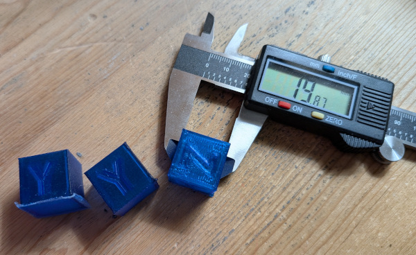
A 20mm block printed at 19.87mm (YYZ for Todd)
Looking around online confirmed that Kobra-2 prints were just slightly smaller than they're supposed to be. To make matters worse, the printer's menu doesn't have any settings to help you scale the steps per mm. I wound up downloading a simple calibration cube so I could manually figure out the right scaling value to use in Prusa. After several iterations, the scaling value I settled on was 100.7%. People say there are some adjustments you can have the slicer insert into the gcode stream, but for now I'm just going to plug this scaling value in on anything that needs to be sized accurately.
Making the Arms Weaker by Mistake
Since the original arms seemed to be a little thin, I loaded up the model in Blender and added a modified cube on each end to make a thicker connector. Printing went fine, but when I started pulling off the support structure I managed to rip apart the connector. I've had bad luck removing PLA supports so I printed the whole headrest again (3 hours) and tried removing the supports more carefully. No luck- the arm broke in about the same spot. I took look at it with magnifying glasses and noticed that the break was pretty clean, almost as if there was an empty spot in the arm. I went back to Prusa to look at the print and found that there was a hole exactly where I'd put the second block.
Started off good, but I wound up making it worse
I'm not sure how I got it wrong in Blender. My guess is that when I added the block I did a binary difference instead of union. I redid the blocks, verified the arms were solid in Prusa, and printed again.
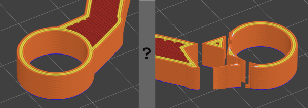
Problems with Ledges
I thought I'd ironed out all the problems when I got to this point, but no- I started getting prints that had one or two major alignment problems (ie, the whole design shifted in the Y by a few millimeters). I don't care how things look, but the shifts were big enough that the switch connector didn't fit all the way into the socket. I had two failed prints with a design that tried to minimize supports and then another that was vertical. I hadn't had problems like this before, so I suspected that some Z adjustments I'd made earlier were to blame. Resetting the Z height to the value where I'd started fixed things.
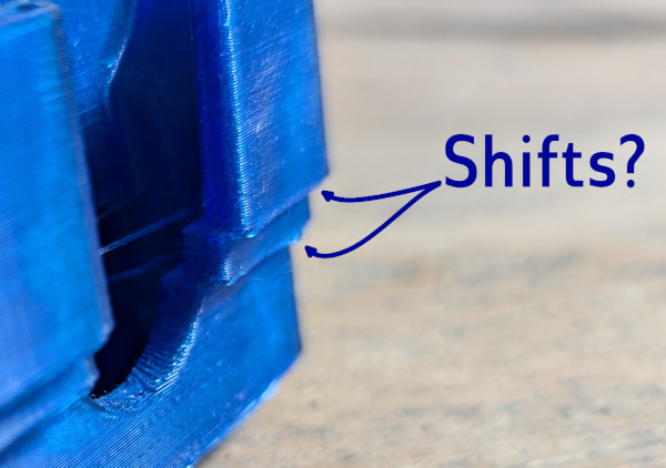
Everything shifted right twice
Finished
So there, after many missteps I successfully printed both the switch holder and the armrest attachment. Was it worth it? Well, no, not really, if the end goal was just to print things from the web. The headrest part took at least 8 tries before I got it right (and at least 3 tries for the holder), each one taking a few hours to grind away. Prints are easy to setup, but that's a lot of wasted plastic.
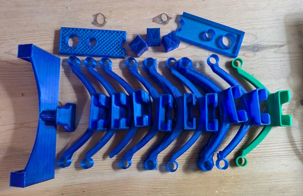
Mistakes were made
However, I learned a lot from seeing this print all the way through. I now know: designs need to be scaled by 1.007x to be accurate, check the layers there aren't unexpected holes in a design; each first layer island increases the probability of an island popping off and causing failure; and being too high in the Z dimension can lead to shifts that won't happen until later in the print.

